|
|
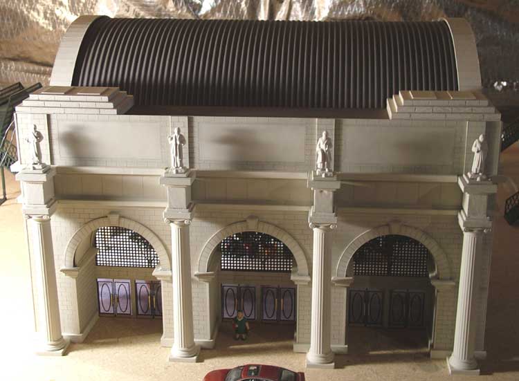
For several weeks, I stood the Main Hall front up on our kitchen counter, with the columns placed in front, and just tried to imagine how this station would really look with the rest of it built. Due to the expense of lasering custom styrene sheets, I limited myself to no more than one elevation design per month. This usually worked out well, since it typically takes me about a month to frame, paint, weather, and finish a single building wall.
It was time to start the side walls to the Main Hall. A large building wall, with etching detail on only one side, tends to cause the plastic part to "cup", or warp a little around the etched face. This is natural, and must be combatted with solid structural framing. The first thing I do with these parts is clean them gently with a damp paper towel, to get rid of the dust resulting from the lasering process. Next, I typically cut wooden square dowel parts to serve as internal framing. Usually, there is a lateral piece that runs the length of the wall horizontally. I used 3/8" square wooden dowel for this, and these lateral beams are typically mounted so that there is about a 1/2" of space between the top of the beam, and the top of the building edge. This is because my roofing systems are almost always recessed a bit into the top of the building.
|
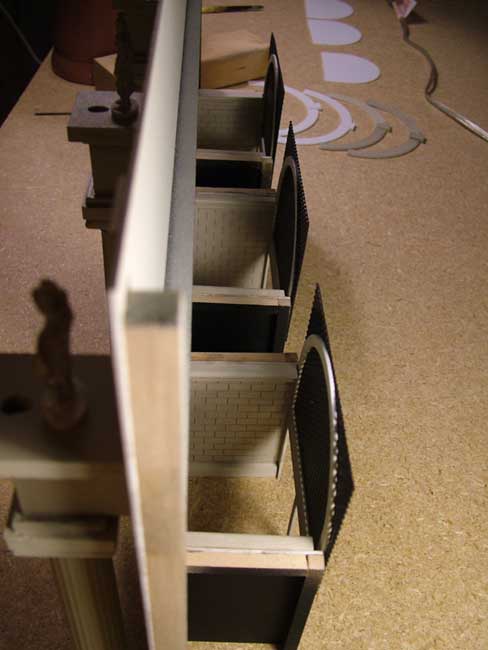
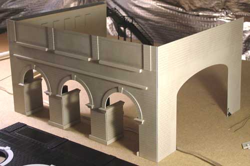
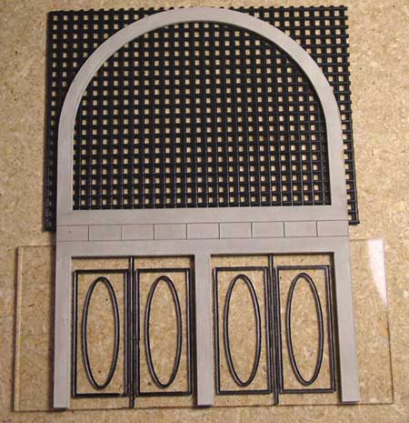
Looking at the Main Hall front wall from the side, before the barrel ceilings were installed.
|
After framing, I try to assemble as much of the exterior detailing as possible. For the Main Hall this included the "eyebrows" and keystones over each arch portal, the upraised plates behind each statue, and some of the ledge moulding that is integrated with the column headers. Then I paint the piece with the limestone spray paint. One, medium coat is all I used, and I found this allowed a trace of the black base color of the plastic styrene to accent the limestone, which I think worked very well with the blackwash weathering.
When the sandstone paint is completely dry, I applied an India ink & alchohol blackwash to the entire surface using a cheap, medium sized modelers paint brush. This is something that takes a bit of experimentation to get comfortable with, but I think the results are terrific.
|
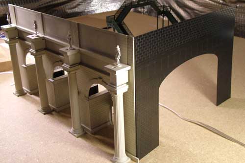
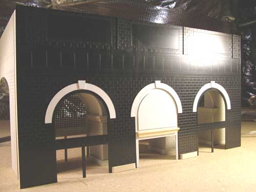
The Main Hall with one of the side walls placed next to it before it was painted, etc.
|
The corners of these buildings need to be supported by something, since the building faces are so thin (1/16" styrene). I used the same 3/8" square dowels, and used Walther's Goo to affix the corner struts to the back side of the styrene walls. I simply glued these corner struts flush with the vertical edges of the walls, which created a 1/16" corner "notch" on the exterior of the corners of the building. These were "filled in" with 1/16" wooden square sticks after the whole building was assembled. The ideal way to do this is to have your brick pattern actually cut out in a squared-off "zig-zag" pattern on each side. Then, take the trouble to ensure that wherever two sides are going to be assembled together, that their brick pattern cutouts fit together perfectly like a jig-saw puzzle. In this way, you will have very realistic corners, without the need for my little "cheat" with the vertical sticks to cover up the resulting notches. Doing the bricks in this zig-zag way for the edges requires using thicker walls - ideally, the walls would need to be about as thick as each brick is tall. With my thin 1/16" walls, these kinds of corners would have looked very odd.
That's about it for the basic construction techniques. There's really nothing "masterful" about it - this part of the modeling process is pretty straightforward; almost mundane. The only thing to note about it is that if you are planning to finish the interior of your model, then you need to take greater care with the planning and execution of the internal framing. It's not at all difficult to get yourself into a pickle if you don't think it through carefully. And this is where CAD design can really help. With your building elevation sides all designed in CADs, you can easily pull them all in together within the drawing software, and the computer can show you how they will look when assembled. This can, and often did, reveal potential problems before they were carved into styrene for me. For example, when I designed the side walls to the Main Hall, I accidentally placed the "cigar band" of vertical lines too high. When I placed that design adjacent to that of the Main Hall front, it was obvious the etching patterns would not align properly. So I was able to correct it before it was sent to the laser shop. The rear wall of the Main Hall was next, and by this time I was gaining more confidence in both the CAD design process, and the accuracy of the laser machine. With all four sides of the Main Hall painted, weathered, and assembled, and the columns with statues placed in front, I was startled at the results. So far, this model was exceeding my expectations.
|
|
|
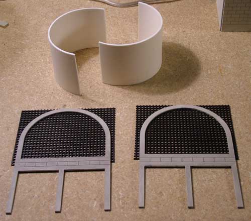
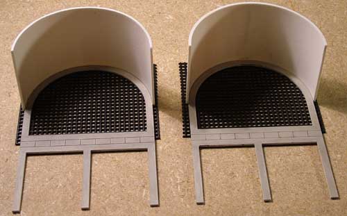
Two pieces of cut PVC pipe, used for the barrel ceilings of two arch portals.
|
Sooner or later I knew I had to do something for the barrel ceilings of the front arch portals. I had been through the PVC pipe aisle of Home Depot a few times, taking measurements of the various available diameters, and had noticed that there was one inexpensive pipe which would likely work. So I bought the pipe, and began to experiment with it to see how it might fare out.
I cut the PVC pipe to the right length - 2.5 inches - and then cut the resulting cylinder in half to get two half-barrel shapes. Then, I dry-fitted them into place around the arch portal door faces. The biggest issue was eliminating the visual "gap" around the circumference, and I did this with additional plastic strips glued into place. Then I needed to secure the base edges with wooden strips, to help prevent the barrels from sliding out of place over time. The result worked reasonably well, although not as perfect as I would have liked. If I were to do this again, I think I might try bending brass sheet to form these barrel ceilings.
|
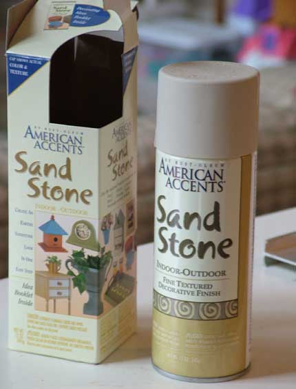
The "limestone" paint used for almost the entire project.
|
The paint I used for the "limestone" of most of the station is American Accents Sandstone product. I found this originally at Home Depot, and bought several cans of it in hopes it would last for the entire project. This paint has a texture to it which lends more realism to it as a limestone surface, which is nice. But the sand in the spray can causes the nozzles to clog very easily, and I ended up throwing several cans in the trash, even when they had plenty of paint left.
This got very frustrating, and I ended up purchasing extra nozzles from an on-line store, which saved me from wasting perhaps a dozen of these spray cans. As if that weren't enough, at some point in the middle of the project, Home Depot, Lowes, and Michael's craft store all stopped carrying this particular color. I still had a couple cans left, so I immediately made a color card with some of it, and then had the color matched at a local paint store. I figured if I got desperate, I could borrow my father's airbrush equipment and spray my pieces with that paint. A new craft store opened up in our area, called A.C. Moore, and they carry this line and color of spray paint, so I have yet to resort to the airbrush technique. Still, having the extra paint available for simple touch-ups has proven worthwhile.
|
|
|
The Main Hall with both side walls installed, and the rear elevation of the Main Hall, posed for placement before finishing.
|
I had experimented with lighting up the individual statues early in the process, very shortly after I'd aquired the columns. This was done with very small incandescent bulbs. They are mounted directly in front of each statue, at the base, and cast an upward glow on them. The effect is something I really like, although it is totally ficticious, since the statues on the real WUS do not have lights. But the indirect lighting, at such a shallow angle, casts highlights and shadows upwards on the station's face, giving the illusion of greater height.
|
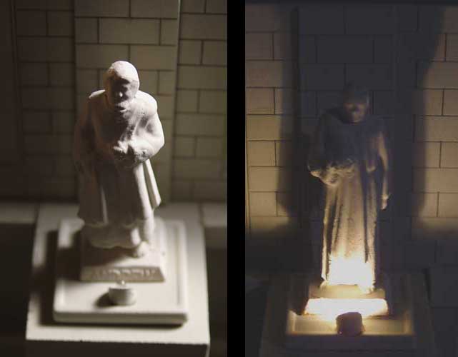
Statuary of the Main Hall. The left shows one with the accent light off, with the overhead lighting of the room on.
The right shows a different statue with the room lights off, and the accent lights on.
|
Getting the lights mounted in such a way that the bulbs could be exchanged in the event of burnouts turned out to be trickier than I'd expected. In the end, I curved the bulb wires back up under the statue bases, and then drilled holes into the main facade so the wires could go into the station above the arch portals. This works out well, as the arch portals form a 2.5" space to deal with wiring harnesses, terminal blocks, etc.
|
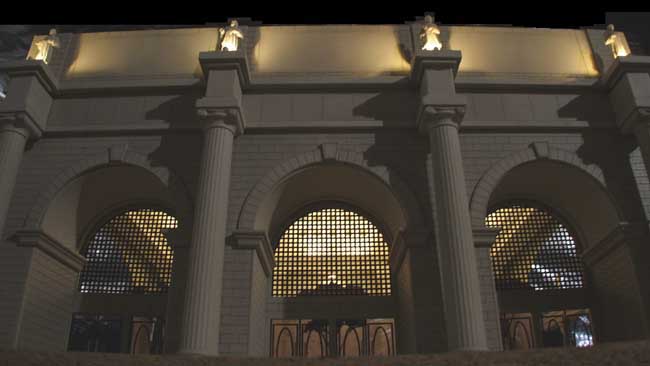
This was taken after the Main Hall barrel ceiling was intalled, which you can barely make out here.
|
For reasons to be explained in the next section (on the barrel vault), I soon became eager to finish the interior of the Main Hall. Before I could do this, however, I needed to get the "glass" components installed. This is because the glass doors and windows of the station are all "sandwiched" between the exterior elevation, and the interior facade.
I looked around at what was available for custom windows - Grandt Line, as well as some doll house suppliers make some really neat things. But due to the highly specific size and shape of all the windows and doors on this model, I was unable to find anything that would suffice. I had figured this would be the case. So I started experimenting with another idea for using the CAD/lasering technique. By designing etches to look like the window pane grilles, or "mullions", I could have these designs etched into clear plastic sheet, but have the laser shop leave the masking on. In this way, the laser will etch right through the masking, leaving me a perfect paint mask to paint the "mullions" whatever color I wanted.
|
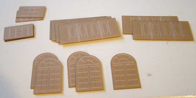
Here's a photo of the very first set of "glass" components I had ordered.
|
The Main Hall really only has six twin sets of double-doors, and nothing else in the way of glass. But I knew I wanted to at least try a few palladian windows, as well as some of the rectangular windows for the eventual connecting halls, in this first, experimental glass sheet.
The doors to the Main Hall simply have a "door" pattern etched into them. These are not based on the real train station, but just a simple pattern I invented for this model. By painting two coats of black enamel into the etches, then waiting for the paint to thoroughly dry, I was able to peel off the masking, revealing door sets with a mullion pattern both etched and painted into the surface.
|
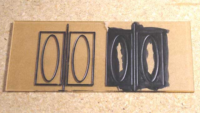
Here's a photo of one of the Main Hall's double-door sets getting painted.
|
You can see from the photos that this clear plastic, about the same thickness as the 1/16" black styrene used for the exterior and interior facades, can simply be glued into place behind the exterior.
I had some trouble with the rectangular windows, used for the upper level of the connecting halls. These windows have wider mullions, and this left a wider "etch" groove into the plastic. I started to experience trouble with many of these windows (there are 20 in all) when, after painting the etched grooves the patina green color, pulling off the masking caused some of the paint to tear in uneven lines. This left a very unsightly "fuzzy", or flakey edge to all the mullions. Several attempts later, I learned that by thinning out the paint slightly with water, and applying two or three light coats of paint, the flaking was much less severe. Also, I asked the laser shop to etch deeper into the plastic, which helped as well.
|
I eventualy ended up tinting the doors all over the station, as I felt they were too "bright".
|
With the glass components installed in the Main Hall, it was time to decide how to proceed next. If you take a look at the side walls to the Main Hall, you'll see they have large, elliptically-arched openings in them. This is because I intended them to open up internally to the "connecting halls", which would in turn open up internally to the East & West Halls (the smaller sub-buildings at the extreme wings of the station).
My WUS model is essentially three distinct buildings, connected together by four single walls, which I've always called "connecting halls". The edges of these single walls insert into grooves on the adjacent buildings created by gluing square wooden strips at the right places. (This is better shown in the photos than described with words.) So I figured the next logical step would be to create the extreme East & West Hall buildings, the designs of which I had already just about completed. Once those were built, it would be a simple matter of getting the connecting hall pieces constructed, and inserting them into place. Seemed simple enough...
|